Harmonic drive
Main article:
Harmonic driveA
harmonic drive is a specialized
proprietary gearing mechanism.
[edit] Cage gear
A
cage gear, also called a
lantern gear or
lantern pinion has cylindrical rods for teeth, parallel to the axle and arranged in a circle around it, much as the bars on a round bird cage or lantern. The assembly is held together by disks at either end into which the tooth rods and axle are set.
[edit] Nomenclature
[edit] General nomenclature
- Rotational frequency, n
- Measured in rotation over time, such as RPM.
- Angular frequency, ω
- Measured in radians per second. 1RPM = π / 30 rad/second
- Number of teeth, N
- How many teeth a gear has, an integer. In the case of worms, it is the number of thread starts that the worm has.
- Gear, wheel
- The larger of two interacting gears.
- Pinion
- The smaller of two interacting gears.
- Path of contact
- Path followed by the point of contact between two meshing gear teeth.
- Line of action, pressure line
- Line along which the force between two meshing gear teeth is directed. It has the same direction as the force vector. In general, the line of action changes from moment to moment during the period of engagement of a pair of teeth. For involute gears, however, the tooth-to-tooth force is always directed along the same line—that is, the line of action is constant. This implies that for involute gears the path of contact is also a straight line, coincident with the line of action—as is indeed the case.
- Axis
- Axis of revolution of the gear; center line of the shaft.
- Pitch point, p
- Point where the line of action crosses a line joining the two gear axes.
- Pitch circle, pitch line
- Circle centered on and perpendicular to the axis, and passing through the pitch point. A predefined diametral position on the gear where the circular tooth thickness, pressure angle and helix angles are defined.
- Pitch diameter, d
- A predefined diametral position on the gear where the circular tooth thickness, pressure angle and helix angles are defined. The standard pitch diameter is a basic dimension and cannot be measured, but is a location where other measurements are made. Its value is based on the number of teeth, the normal module (or normal diametral pitch), and the helix angle. It is calculated as:
 in metric units or
  in imperial units.[15]
- Module, m
- A scaling factor used in metric gears with units in millimeters who's effect is to enlarge the gear tooth size as the module increases and reduce the size as the module decreases. Module can be defined in the normal (mn), the transverse (mt), or the axial planes (ma) depending on the design approach employed and the type of gear being designed.[15] Module is typically an input value into the gear design and is seldom calculated.
- Operating pitch diameters
- Diameters determined from the number of teeth and the center distance at which gears operate.[4] Example for pinion:

- Pitch surface
- In cylindrical gears, cylinder formed by projecting a pitch circle in the axial direction. More generally, the surface formed by the sum of all the pitch circles as one moves along the axis. For bevel gears it is a cone.
- Angle of action
- Angle with vertex at the gear center, one leg on the point where mating teeth first make contact, the other leg on the point where they disengage.
- Arc of action
- Segment of a pitch circle subtended by the angle of action.
- Pressure angle, θ
- The complement of the angle between the direction that the teeth exert force on each other, and the line joining the centers of the two gears. For involute gears, the teeth always exert force along the line of action, which, for involute gears, is a straight line; and thus, for involute gears, the pressure angle is constant.
- Outside diameter, Do
- Diameter of the gear, measured from the tops of the teeth.
- Root diameter
- Diameter of the gear, measured at the base of the tooth.
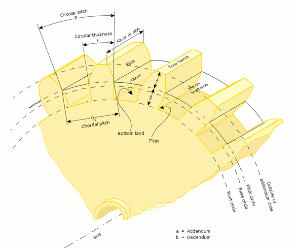
- Addendum, a
- Radial distance from the pitch surface to the outermost point of the tooth. a = (Do − D) / 2
- Dedendum, b
- Radial distance from the depth of the tooth trough to the pitch surface. b = (D − rootdiameter) / 2
- Whole depth, ht
- The distance from the top of the tooth to the root; it is equal to addendum plus dedendum or to working depth plus clearance.
- Clearance
- Distance between the root circle of a gear and the addendum circle of its mate.
- Working depth
- Depth of engagement of two gears, that is, the sum of their operating addendums.
- Circular pitch, p
- Distance from one face of a tooth to the corresponding face of an adjacent tooth on the same gear, measured along the pitch circle.
- Diametral pitch, pd
- Ratio of the number of teeth to the pitch diameter. Could be measured in teeth per inch or teeth per centimeter.
- Base circle
- In involute gears, where the tooth profile is the involute of the base circle. The radius of the base circle is somewhat smaller than that of the pitch circle.
- Base pitch, normal pitch, pb
- In involute gears, distance from one face of a tooth to the corresponding face of an adjacent tooth on the same gear, measured along the base circle.
- Interference
- Contact between teeth other than at the intended parts of their surfaces.
- Interchangeable set
- A set of gears, any of which will mate properly with any other.
[edit] Helical gear nomenclature
- Helix angle, ψ
- Angle between a tangent to the helix and the gear axis. Is zero in the limiting case of a spur gear.
- Normal circular pitch, pn
- Circular pitch in the plane normal to the teeth.
- Transverse circular pitch, p
- Circular pitch in the plane of rotation of the gear. Sometimes just called "circular pitch". pn = pcos(ψ)
Several other helix parameters can be viewed either in the normal or transverse planes. The subscript n usually indicates the normal.
[edit] Worm gear nomenclature
- Lead
- Distance from any point on a thread to the corresponding point on the next turn of the same thread, measured parallel to the axis.
- Linear pitch, p
- Distance from any point on a thread to the corresponding point on the adjacent thread, measured parallel to the axis. For a single-thread worm, lead and linear pitch are the same.
- Lead angle, λ
- Angle between a tangent to the helix and a plane perpendicular to the axis. Note that it is the complement of the helix angle which is usually given for helical gears.
- Pitch diameter, dw
- Same as described earlier in this list. Note that for a worm it is still measured in a plane perpendicular to the gear axis, not a tilted plane.
Subscript w denotes the worm, subscript g denotes the gear.
[edit] Tooth contact nomenclature
| | | | |
Lines of contact (helical gear)
| | | |
| | |
- Point of contact
- Any point at which two tooth profiles touch each other.
- Line of contact
- A line or curve along which two tooth surfaces are tangent to each other.
- Path of action
- The locus of successive contact points between a pair of gear teeth, during the phase of engagement. For conjugate gear teeth, the path of action passes through the pitch point. It is the trace of the surface of action in the plane of rotation.
- Line of action
- The path of action for involute gears. It is the straight line passing through the pitch point and tangent to both base circles.
- Surface of action
- The imaginary surface in which contact occurs between two engaging tooth surfaces. It is the summation of the paths of action in all sections of the engaging teeth.
- Plane of action
- The surface of action for involute, parallel axis gears with either spur or helical teeth. It is tangent to the base cylinders.
- Zone of action (contact zone)
- For involute, parallel-axis gears with either spur or helical teeth, is the rectangular area in the plane of action bounded by the length of action and the effective face width.
- Path of contact
- The curve on either tooth surface along which theoretical single point contact occurs during the engagement of gears with crowned tooth surfaces or gears that normally engage with only single point contact.
- Length of action
- The distance on the line of action through which the point of contact moves during the action of the tooth profile.
- Arc of action, Qt
- The arc of the pitch circle through which a tooth profile moves from the beginning to the end of contact with a mating profile.
- Arc of approach, Qa
- The arc of the pitch circle through which a tooth profile moves from its beginning of contact until the point of contact arrives at the pitch point.
- Arc of recess, Qr
- The arc of the pitch circle through which a tooth profile moves from contact at the pitch point until contact ends.
- Contact ratio, mc, ε
- The number of angular pitches through which a tooth surface rotates from the beginning to the end of contact.In a simple way, it can be defined as a measure of the average number of teeth in contact during the period in which a tooth comes and goes out of contact with the mating gear.
- Transverse contact ratio, mp, εα
- The contact ratio in a transverse plane. It is the ratio of the angle of action to the angular pitch. For involute gears it is most directly obtained as the ratio of the length of action to the base pitch.
- Face contact ratio, mF, εβ
- The contact ratio in an axial plane, or the ratio of the face width to the axial pitch. For bevel and hypoid gears it is the ratio of face advance to circular pitch.
- Total contact ratio, mt, εγ
- The sum of the transverse contact ratio and the face contact ratio.
- εγ = εα + εβ
- mt = mp + mF
- Modified contact ratio, mo
- For bevel gears, the square root of the sum of the squares of the transverse and face contact ratios.

- Limit diameter
- Diameter on a gear at which the line of action intersects the maximum (or minimum for internal pinion) addendum circle of the mating gear. This is also referred to as the start of active profile, the start of contact, the end of contact, or the end of active profile.
- Start of active profile (SAP)
- Intersection of the limit diameter and the involute profile.
- Face advance
- Distance on a pitch circle through which a helical or spiral tooth moves from the position at which contact begins at one end of the tooth trace on the pitch surface to the position where contact ceases at the other end.
[edit] Tooth thickness nomeclature
| | | | Tooth thickness measurement over pins
|
| | Long and short addendum teeth
|
- Circular thickness
- Length of arc between the two sides of a gear tooth, on the specified datum circle.
- Transverse circular thickness
- Circular thickness in the transverse plane.
- Normal circular thickness
- Circular thickness in the normal plane. In a helical gear it may be considered as the length of arc along a normal helix.
- Axial thickness
- In helical gears and worms, tooth thickness in an axial cross section at the standard pitch diameter.
- Base circular thickness
- In involute teeth, length of arc on the base circle between the two involute curves forming the profile of a tooth.
- Normal chordal thickness
- Length of the chord that subtends a circular thickness arc in the plane normal to the pitch helix. Any convenient measuring diameter may be selected, not necessarily the standard pitch diameter.
- Chordal addendum (chordal height)
- Height from the top of the tooth to the chord subtending the circular thickness arc. Any convenient measuring diameter may be selected, not necessarily the standard pitch diameter.
- Profile shift
- Displacement of the basic rack datum line from the reference cylinder, made non-dimensional by dividing by the normal module. It is used to specify the tooth thickness, often for zero backlash.
- Rack shift
- Displacement of the tool datum line from the reference cylinder, made non-dimensional by dividing by the normal module. It is used to specify the tooth thickness.
- Measurement over pins
- Measurement of the distance taken over a pin positioned in a tooth space and a reference surface. The reference surface may be the reference axis of the gear, a datum surface or either one or two pins positioned in the tooth space or spaces opposite the first. This measurement is used to determine tooth thickness.
- Span measurement
- Measurement of the distance across several teeth in a normal plane. As long as the measuring device has parallel measuring surfaces that contact on an unmodified portion of the involute, the measurement will be along a line tangent to the base cylinder. It is used to determine tooth thickness.
- Modified addendum teeth
- Teeth of engaging gears, one or both of which have non-standard addendum.
- Full-depth teeth
- Teeth in which the working depth equals 2.000 divided by the normal diametral pitch.
- Stub teeth
- Teeth in which the working depth is less than 2.000 divided by the normal diametral pitch.
- Equal addendum teeth
- Teeth in which two engaging gears have equal addendums.
- Long and short-addendum teeth
- Teeth in which the addendums of two engaging gears are unequal.
[edit] Pitch nomenclature
Pitch is the distance between a point on one tooth and the corresponding point on an adjacent tooth.
[4] It is a dimension measured along a line or curve in the transverse, normal, or axial directions. The use of the single word
pitch without qualification may be ambiguous, and for this reason it is preferable to use specific designations such as transverse circular pitch, normal base pitch, axial pitch.
- Circular pitch, p
- Arc distance along a specified pitch circle or pitch line between corresponding profiles of adjacent teeth.
- Transverse circular pitch, pt
- Circular pitch in the transverse plane.
- Normal circular pitch, pn, pe
- Circular pitch in the normal plane, and also the length of the arc along the normal pitch helix between helical teeth or threads.
- Axial pitch, px
- Linear pitch in an axial plane and in a pitch surface. In helical gears and worms, axial pitch has the same value at all diameters. In gearing of other types, axial pitch may be confined to the pitch surface and may be a circular measurement. The term axial pitch is preferred to the term linear pitch. The axial pitch of a helical worm and the circular pitch of its worm gear are the same.
- Normal base pitch, pN, pbn
- An involute helical gear is the base pitch in the normal plane. It is the normal distance between parallel helical involute surfaces on the plane of action in the normal plane, or is the length of arc on the normal base helix. It is a constant distance in any helical involute gear.
- Transverse base pitch, pb, pbt
- In an involute gear, the pitch on the base circle or along the line of action. Corresponding sides of involute gear teeth are parallel curves, and the base pitch is the constant and fundamental distance between them along a common normal in a transverse plane.
- Diametral pitch (transverse), Pd
- Ratio of the number of teeth to the standard pitch diameter in inches.

- Normal diametral pitch, Pnd
- Value of diametral pitch in a normal plane of a helical gear or worm.

- Angular pitch, θN, τ
- Angle subtended by the circular pitch, usually expressed in radians.
 degrees or
  radians
[edit] Backlash
Backlash is the error in motion that occurs when gears change direction. It exists because there is always some gap between the trailing face of the driving tooth and the leading face of the tooth behind it on the driven gear, and that gap must be closed before force can be transferred in the new direction. The term "backlash" can also be used to refer to the size of the gap, not just the phenomenon it causes; thus, one could speak of a pair of gears as having, for example, "0.1 mm of backlash." A pair of gears could be designed to have zero backlash, but this would presuppose perfection in manufacturing, uniform thermal expansion characteristics throughout the system, and no lubricant. Therefore, gear pairs are designed to have some backlash. It is usually provided by reducing the tooth thickness of each gear by half the desired gap distance. In the case of a large gear and a small pinion, however, the backlash is usually taken entirely off the gear and the pinion is given full sized teeth. Backlash can also be provided by moving the gears farther apart.
For situations, such as instrumentation and control, where precision is important, backlash can be minimised through one of several techniques. For instance, the gear can be split along a plane perpendicular to the axis, one half fixed to the shaft in the usual manner, the other half placed alongside it, free to rotate about the shaft, but with springs between the two halves providing relative torque between them, so that one achieves, in effect, a single gear with expanding teeth. Another method involves tapering the teeth in the axial direction and providing for the gear to be slid in the axial direction to take up slack.
[edit] Shifting of gears
In some machines (e.g., automobiles) it is necessary to alter the gear ratio to suit the task. There are several methods of accomplishing this. For example:
There are several outcomes of gear shifting in motor vehicles. In the case of
air pollution emissions, there are higher pollutant emissions generated in the lower gears, when the engine is working harder than when higher gears have been attained. In the case of
vehicle noise emissions, there are higher
sound levels emitted when the vehicle is engaged in lower gears. This fact has been utilized in analyzing vehicle generated sound since the late 1960s, and has been incorporated into the simulation of urban roadway noise and corresponding design of urban
noise barriers along roadways.
[16]
[edit] Tooth profile
A profile is one side of a tooth in a cross section between the outside circle and the root circle. Usually a profile is the curve of intersection of a tooth surface and a plane or surface normal to the pitch surface, such as the transverse, normal, or axial plane.
The fillet curve (root fillet) is the concave portion of the tooth profile where it joins the bottom of the tooth space.
2
As mentioned near the beginning of the article, the attainment of a non fluctuating velocity ratio is dependent on the profile of the teeth.
Friction and wear between two gears is also dependent on the tooth profile. There are a great many tooth profiles that will give a constant velocity ratio, and in many cases, given an arbitrary tooth shape, it is possible to develop a tooth profile for the mating gear that will give a constant velocity ratio. However, two constant velocity tooth profiles have been by far the most commonly used in modern times. They are the
cycloid and the involute. The cycloid was more common until the late 1800s; since then the involute has largely superseded it, particularly in drive train applications. The cycloid is in some ways the more interesting and flexible shape; however the involute has two advantages: it is easier to manufacture, and it permits the center to center spacing of the gears to vary over some range without ruining the constancy of the velocity ratio. Cycloidal gears only work properly if the center spacing is exactly right. Cycloidal gears are still used in mechanical clocks.
An
undercut is a condition in generated gear teeth when any part of the fillet curve lies inside of a line drawn tangent to the working profile at its point of juncture with the fillet. Undercut may be deliberately introduced to facilitate finishing operations. With undercut the fillet curve intersects the working profile. Without undercut the fillet curve and the working profile have a common tangent.
[edit] Gear materials
Numerous nonferrous alloys, cast irons, powder-metallurgy and even plastics are used in the manufacture of gears. However steels are most commonly used because of their high strength to weight ratio and low cost. Plastic is commonly used where cost or weight is a concern. A properly designed plastic gear can replace steel in many cases because it has many desirable properties, including dirt tolerance, low speed meshing, and the ability to "skip" quite well. Manufacturers have employed plastic gears to make consumer items affordable in items like copy machines, optical storage devices, VCRs, cheap dynamos, consumer audio equipment, servo motors, and printers.
[edit] The module system
Countries which have adopted the
metric system generally use the module system. As a result, the term module is usually understood to mean the pitch diameter in millimeters divided by the number of teeth. When the module is based upon inch measurements, it is known as the
English module to avoid confusion with the metric module. Module is a direct dimension, whereas diametral pitch is an inverse dimension (like "threads per inch"). Thus, if the pitch diameter of a gear is 40 mm and the number of teeth 20, the module is 2, which means that there are 2 mm of pitch diameter for each tooth.
[17]
[edit] Manufacture
Gear are most commonly produced via
hobbing, but they are also
shaped,
broached,
cast, and in the case of plastic gears,
injection molded. For metal gears the teeth are usually
heat treated to make them hard and more
wear resistant while leaving the core soft and
tough. For large gears that are prone to warp a
quench press is used.
[edit] Gear model in modern physics
Modern physics adopted the gear model in different ways. In nineteenth century
James Clerk Maxwell developed a model of electromagnetism in which magnetic field lines were rotating tubes of incompressible fluid. Maxwell used gear wheel and called it “idle wheel” to explain the electrical current as a rotation of particles in opposite direction to that of the rotating field lines.
[18]
A new consideration of gear in
quantum physics is regarded as a quantum gears. A group of gears can serve as a model for several different systems such as an artificially constructed nanomechanical device or a group of ring molecules.
[19]
It has been shown that the Three Wave Hypothesis may be represented in a bevel gear form.
[20]
[edit] See also
[edit] References
- ^ Howstuffworks "Transmission Basics"
- ^ Norton 2004, p. 462
- ^ M.J.T. Lewis: "Gearing in the Ancient World", Endeavour, Vol. 17, No. 3 (1993), pp. 110–115 (110)
- ^ a b c d ANSI/AGMA 1012-G05, "Gear Nomenclature, Definition of Terms with Symbols".
- ^ Doughtie and Vallance give the following information on helical gear speeds: "Pitch-line speeds of 4,000 to 7,000 fpm [20 to 36 m/s] are common with automobile and turbine gears, and speeds of 12,000 fpm [61 m/s] have been successfully used." -- p.281.
- ^ a b Helical gears, retrieved 2009-06-15.
- ^ McGraw Hill Encyclopedia of Science and Technology, "Gear", p. 742.
- ^ Canfield, Stephen (1997), "Gear Types", Dynamics of Machinery, Tennessee Tech University, Department of Mechanical Engineering, ME 362 lecture notes.
- ^ Hilbert, David; Cohn-Vossen, Stephan (1952), Geometry and the Imagination (2nd ed.), New York: Chelsea, pp. 287, ISBN 978-0-8284-1087-8.
- ^ McGraw Hill Encyclopedia of Science and Technology, "Gear, p. 743.
- ^ Vallance Doughtie, p. 287.
- ^ Vallance Doughtie, pp. 280, 296.
- ^ Doughtie and Vallance, p. 290; McGraw Hill Encyclopedia of Science and Technology, "Gear", p. 743.
- ^ McGraw Hill Encyclopedia of Science and Technology, "Gear", p. 744.
- ^ a b ISO/DIS 21771:2007 : "Gears - Cylindrical Involute Gears and Gear Pairs - Concepts and Geometry", International Organization for Standardization, (2007)
- ^ C Michael Hogan and Gary L Latshaw,The Relationship Between Highway Planning and Urban Noise , Proceedings of the ASCE, Urban Transportation Division Specialty Conference by the American Society of Civil Engineers, Urban Transportation Division, May 21 to 23, 1973, Chicago, Illinois
- ^ Oberg, E; Jones, F.D.; Horton, H.L.; Ryffell, H.H. (2000), Machinery's Handbook (26th ed.), Industrial Press, pp. 2649, ISBN 978-0-8311-2666-7.
- ^ Innovation in Maxwell's Electromagnetic Theory: Molecular Vortices, Displacement Current, and Light Daniel M. Siegel. University of Chicago Press (1991)
- ^ Angus MacKinnon arxiv (2002) http://arxiv.org/abs/cond-mat/0205647v2
- ^ M. I. Sanduk, Does the Three Wave Hypothesis Imply Hidden Structure? Apeiron, 14, No. 2, pp. 113-125 (2007)
[edit] Bibliography
- American Gear Manufacturers Association; American National Standards Institute (2005), Gear Nomenclature, Definitions of Terms with Symbols (ANSI/AGMA 1012-F90 ed.), American Gear Manufacturers Association, ISBN 9781555898465.
- McGraw-Hill (2007), McGraw-Hill Encyclopedia of Science and Technology (10th ed.), McGraw-Hill Professional, ISBN 978-0071441438.
- Norton, Robert L. (2004), Design of Machinery (3rd ed.), McGraw-Hill Professional, ISBN 9780071214964.
- Vallance, Alex; Doughtie, Venton Levy (1964), Design of machine members (4th ed.), McGraw-Hill.
[edit] Further reading


